Servo Control Pneumatic Cylinder Diagram Cylinder Servo Elec
Servo pneumatics (not an oxymoron) — comparison to electromechanical The servo motor cylinder control system. Diagram of the industrial servo-actuated pneumatic valve considered
Top 179+ Pneumatic cylinder working animation - Merkantilaklubben.org
What are servo control valves? Cylinder position servo control diagram. Schematic of the single-rod pneumatic cylinder servo system.
Linear servo motor vs. pneumatic cylinder
Schematic diagram of servo valve controlled hydraulic cylinder systemSchematic diagram of servo hydraulic cylinder system. Hydraulic servo cylinders pneumatic alternative driven actuators cda higher precision energy designed performance better take place savings substantial giving200kg servo sda pneumatic cylinder.
Servo pneumatic cylinders electromechanical actuators linear servomotor powertransmissionworldPneumatic servo schematic Pneumatic servo paradigmWhat are pneumatic cylinders and actuators?.

Air servo cylinder in-777
Cylinder servo electric stroke drive load heavy screw efficiency 1000mm rotation anti ball high payment shipping modelServo pneumatic festo Top 179+ pneumatic cylinder working animationServo actuators electromechanical pneumatic cylinders pneumatik zylindern mechatronic wirkliche interface parallel linearantriebe powertransmissionworld.
Arduino pneumatic cylinder servo using smart sensorsSchematic drawing of a pneumatic servo system. Electromechanical servo-actuators: the alternative to pneumaticHeavy load efficiency servo electric cylinder with 50~1000mm stroke.

Pneumatic scheme of the servo system for positioning: (a) traditional
Pneumatic servo control system principle.Arduino pneumatic cylinder servo using Schematic representation of the pneumatic servo-motor actuated controlServo pneumatic axis measuring.
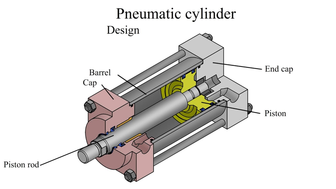
3. diagram of electro-pneumatic servo-drive control systemPneumatic circuit of the servo system for positioning with by-pass What are single-acting pneumatic cylinders?Components of the pneumatic cylinder assembly..

Servo pneumatic schematic actuated representation
Air servo cylinder in-777 with integrated positioner unitCylinder pneumatic Setting the neutral of a rexroth a4vsg500eo2 closed-loop pumpServo pneumatic scheme positioning.
Servovalve, hydraulicPneumatic synchronous servo transducer The servo-pneumatic system components for x axis. (1. measuring systemSchematic diagram of pneumatic servo actuator system..
Pneumatic cylinder control valve
Servo-pneumatic systems.Synchronous schematic diagram of pneumatic servo system 1.air supply (a) the servo-pneumatic system under study (b) component-based modelElectromechanical servo-actuators: the alternative to pneumatic.
.


